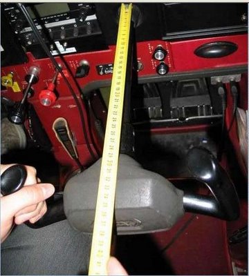
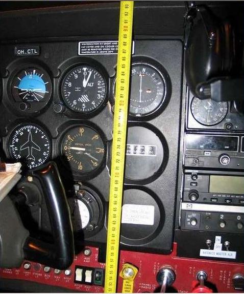
This blogger chronicles the building of a Cessna 172 simulator panel using MS Flight Simulator 2004, joystick peripherals, and actual Cessna parts. The aim is to construct a simulator close enough in dimensions to the real airplane to serve as a humble beginning to eventual real pilot training.

Tuesday, November 21, 2006

Cessna 172 Simulator Panel

FLAPS LEVER
Well, the flaps lever has been a lot of fun to get going.
At first I though about buying an actual Flaps Lever from a Cessna 172 off of e-bay, but after seeing the high auction price on them I figured it was cheaper to get the ol’ noodle thinking.
I found a lawn mower throttle that seem would do the job.


I took it apart and “Viola”: Instant Cessna Flaps Lever for under $8.


I kept some of the alumminum material left over from the panel. Dad and I put some nuts and bolts together for a mechanism that I think will work well and for a long time.

FRONT of panel


Decided to use the same button from the CH YOKE for the flaps by leaving the buttons out of the CH Yoke housing and extending the wires to reach the flaps mechanism. I felt it would be the quickest and easiest way to get the FLAPS LEVER mechanism operational.

BACK of panel

TRIM WHEEL
Using the same button from the CH Yoke is the plan for the TRIM WHEEL mechanism which is currently in the works (will post pics soon).

ADDED REALISM
Oh yea, .... I debated over added realism vs. price for a while. I finally decided to purchase the CESSNA AVIONICS PANEL #1010 from DesktopAviator. I think it looks really good and the added realism should be fun and well worth the price.

http://desktopaviator.com/

PROGRESS THUS FAR
Dad & I decide to take a quick pic of how the panel is shaping up. See what you think.


HAPPY THANKSGIVING 2006 !!!!

Labels: , , , , , , ,

Sunday, October 15, 2006

Cessna 172 Simulator Panel - MS FS 2004

CH YOKE EXTENDED
Last entry, we left our modified CH yoke setting with its new extension.
Obviously, a very technical task since accurate alignment is essential.

BEFORE


AFTER

Side view
As you can see, I left the switches out to extend the wires and place them on the panel as needed.


Top view


PANEL PROGRESS
Continuing on the theme of portability with facility to disassemble, we begin thinking of the actual table that will hold the panel.
We find an old foldout table gathering dust at home that, although not perfect, will do the job.
Dad and I head to the “toy store” (AKA Home Depot) to find some hardware to hold the panel.


Table is a bit high (floor to panel) vs. the actual dimensions of the 172.   None-the-less, we can either cut a small portion of ea leg to lower the panel OR use the panel's current height to simulate some distance off the ground as if to be sitting on the landing gear. We'll see.

Sunday, October 01, 2006

Cessna 172 Simulator

CUTTING THE CH YOKE SHAFT:
Dad had a tube cutter that fit the 1” diameter of the yoke shaft.  The cut is made at the closest point to the yoke itself allowing equal space on either side of the cut shaft to fit couplers without hindering the shaft's full range of motion.


Web photo.  Sorry, don't remember web site.

WIRES:
Once the Yoke shaft is cut, BE EXTREMELY CAREFUL not to cut the entire black cable (which carries 11 wires) all at once because it includes 4 pairs of like colors.
  • 2 Black
  • 2 White
  • 2 Purple
  • 2 Orange
  • 1 Red
  • 1 Blue
  • 1 Green


PVC PIPE PREP:
After careful measurement of all pertinent distances, including the shaft’s forward and aft displacement, we cut the ¾” PVC pipe to the length we need and cover it with Silver Air-Duct tape to make it look like an aluminum pipe.


CH YOKE  -  BUTTON ASSIGNMENT CHECK:
We then run extensions through the PVC pipe, couplers, and faux shaft support and solder the ends to their respective wires.
Before we epoxy all the PVC, Couplers, and Yoke shafts, I hook up the CH Yoke to the CPU and test all button functions and assignments. They all work fine.

Web photo: Michael R. Stiteler (unmodified yoke)

All parts are now setting with fresh epoxy.
I will post the pics of the yoke with extended shaft once epoxy sets.

Sunday, September 24, 2006


Clarification: The PVC pipe used is labeled as ¾” but the outer diameter is just a little larger than 1”.

PANEL CUT:
Had a free day during the week and dropped off the poster board pattern to be cut.
Close to a week later, I pick up the panel – it looks great.


Dad makes a type of grommet to fit over the electrical coupling for a better fit on the panel.


Here is the first look at the panel and the pieces that are to make the yoke.


CUTTING THE CH YOKE SHAFT:

To be posted soon.

COCKPIT / PANEL DESIGN:
Dad and I sit and chat about materials, dimensions, problems, solutions, etc. Meanwhile, mom brings us a couple of cups of coffee and the initial layout starts taking shape.


MUST BE MODULAR:
Possible issues with space and portability required the simulator design to include the facility for taking it apart and reassembly. Therefor a major concern while designing the panel/cockpit.

We use a poster of a Cessna 172 panel from Sporty’s Pilot Shop for reference.

The poster is pretty much exactly as the Cessna 172 panel from MS Flight Simulator, therefore an excellent reference for gauge and other instrument measurements.

Each gauge in a real Cessna is ~ 3” in diameter. On the poster it measures ~6.5cm, so I figured 6.5cm divided by 2.166 = 3". From that we started figuring throttle & mixture knob distances etc.

INCORPORATING THE CH YOKE:
Incorporating the yoke to the sim is a challenge because there are several options and additional challenges with each.

We decide cutting and extending the yoke would be the most realistic option because the shaft in a Cessna 172 extends Full back ~35cm


And goes Full forward ~17cm


Therefore we must extend the yoke shaft to extend ~26 cm from the panel with the yoke at neutral for a more realistic feel.


We take measurements of the Yoke control shaft (~1" diameter) and off to the Hardware store we went.


After much looking over several options and debating over whether to use a metal or plastic tube to extend the yoke shaft, we decide on a ~1” PVC pipe slightly larger than that the yoke shaft.
We chose 1" PVC mostly because it was the only pipe that would fit just right into a 1” electrical coupler that would take the place of a shaft support. 
We figure we can make this work with couplers and possibly epoxy.


POSTER BOARD PATTERN:

With the yoke shaft issue looking good, we buy some poster board and begin making the exact cut-outs carefully measuring monitor sizes and dimensions of all the components such as electrical coupler/yoke, throttle, etc.


CUTTING OUT THE PATTERN:
Now to wait for a day off during the week to take the poster board pattern and have it cut from a aluminum sheet.

Saturday, September 23, 2006

E-BAY to the RESCUE
So I find a monitor (Mobile VU – L3 Communications) that looks to be the needed size on e-bay and have a few days left in the auction to research it and insure the dimensions will fit that tight space above the yoke and the top of the glare shield. The auction states it came from a police car computer system.
I e-mailed the seller to ask about screen size and physical dimensions as well as input connections.
As you may recall, the dimensions of this monitor are the basis of PLAN B, other wise the panel dimensions would be off and it would be back to the drawing board to device a PLAN C.


WHILE I WAIT FOR SELLER RESPONSE
I started to think of PLAN C just in case.

Plan C includes a laptop monitor – but after some research found out that getting a laptop monitor to work with a desktop was close to impossible for issues that are beyond my total understanding.
Another option, with a laptop still in mind, was to unhinge the monitor from the laptop and place the monitor from behind the panel facing forward toward the pilot seat and use that laptop with MS Flight Simulator program.
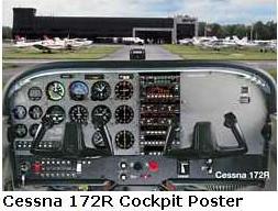
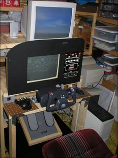
PANEL STRETCHED OVER TWO MONITORS
While brainstorming about the laptop monitor, I begin to figure out how the panel would look if stretched over two monitors (the small monitor above the yoke and one larger in the center of the panel.
My idea is somewhat like this:


SOME CONCLUSIONS
1. MS Flight Simulator is already programmed to handle 2 monitors with no problem:
1 for panel and 1 for scenery:

Michael Neal - Colorado USA
But if I was to use two monitors for panel and one monitor for scenery I was going to have a challenge getting this to work. I’m not a computer wizard by any stretch of the word, but maybe someone on the net had ideas.

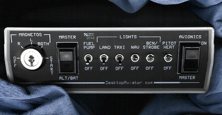
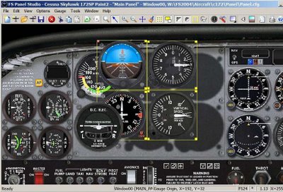
2. Each panel view is going to need some tweaking to include/exclude the gauges I want. Otherwise each view may be full of unneeded gauges or may be missing them.


SELLER WRITES BACK:
The screen size and physical dimensions the seller notes seem right. So, I placed a bid and I WON THE ITEM !


NOW I CAN START
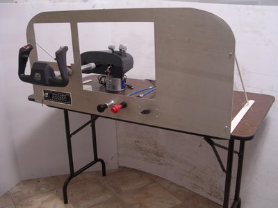
Overcoming the first obstacle (Finding a monitor small enough to fit over the yoke), I started making many drawings on napkins at restaurants and any scratch paper I could doodle on at home and sometimes at work (If you’ve done this, … you’re well on your way to building a sim of your own. lol).
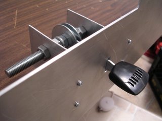
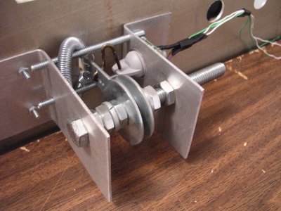
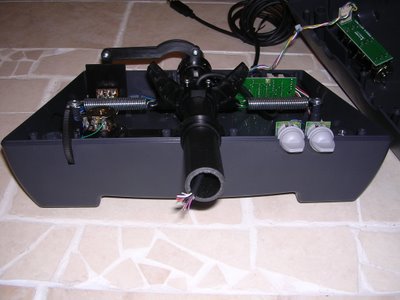
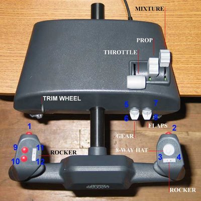
By now I had a rough idea how I would get some Cessna parts to work with my simulator and began searching for some essential parts. Don't have any idea on how to get a trim wheel to work with the sim but will look for one anyhow.
I searched on e-bay for and won:
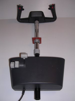
-CH Yoke
-CH Pedals
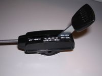
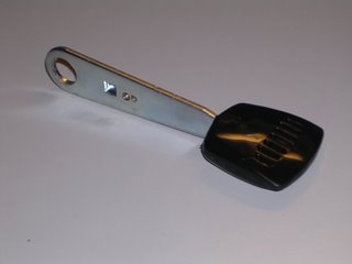
-Cessna 172 Throttle Cable
-Cessna 172 Mixture Cable
-Cessna 150 Trim Wheel (these are hard to find so had to settle for the 150 variety)


WIDEVIEW
I revisit the challenge of getting three monitors/views to work with MS FS and I run into Luciano Napolitano’s awesome program [WideView].
This program allows one to “undock” views and place them in as many monitors as one wants.
Check out this cockpit by Peter Koller using WideView with a LAN:

http://www.wideview.it/


FS PANEL STUDIO
I also revisit the needed tweaking of each monitor view and search the good ‘ol web. I found the FS Panel Studio that does just that. So I ordered the CD version.

http://www.fspanelstudio.com./
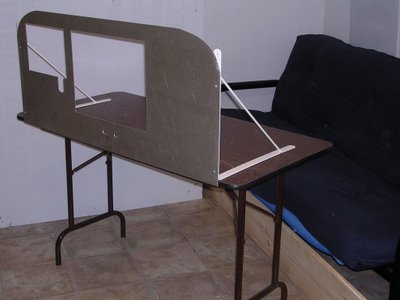


COCKPIT DESIGN
All the mentioned parts are in hand and now on to visit Dad for actual design and eventual construction of the Cockpit.

PLANNING
PLAN A
I first thought about a full-blown panel with actual gauges, yoke, throttle, etc. like this one Michael Neal from Colorado USA built with his Pops and with parts from SIMKITS and CH flight controls

http://www.simkits.com/buildersection.php
http://www.chproducts.com/retail_flash/index.html

I soon realized SIMKITS were quite expensive, so on to Plan B.

PLAN B
“Instead of actual SIMKITS gauges, how about images of the gauges on computer monitors?” I asked myself. This made more financial sense and began researching this possibility.

Prioritizing components:
First: Panel dimensions.
This is first because panel dimensions will dictate monitor sizes and their availability will make or break Plan B.

http://gallery.tigert.com/gallery/c172dim?page=1

From actual Cessna panel measurements, it was clear I only had ~10” from the Yoke bar to top of glare-shield to fit a monitor. I searched the web and e-bay for such a monitor and found either really small monitors or monitors bigger than 10”.
So as far as I’m concerned, the panel project is at a standstill because if I’m unable to find a 10” tall VGA monitor my other option would be to attempt to fit a larger monitor into that space and the distance between the yoke bar and the top of the glare shield will be unrealistically large.


PLAN B STAYS ALIVE:

After several weeks of watching e-bay for a VGA monitor small enough to fit into the ~10” space, one such monitor is listed.  (to be continued soon)

Thursday, September 21, 2006

INTRODUCTION:
This is a father and son project inspired by my fascination with flight since my childhood.
I took my first flight with my pilot uncle in a twin engine plane at about age 5. I remember sitting in the right front seat along side my uncle and although I couldn’t see anything out of the front windshield, I clearly saw a long love affair with flight as my heart pounded with excitement and my mom’s heart pounded with anxiety down on the ground. I think her anxiety was not necessarily her imagining something going terribly wrong in that flight but more precisely the thought of me getting hooked on flying and eventually pursuing a PPL (Private Pilot License) making her feel anxiety of that intensity for much longer than just that 30 minute ride. 

EXPOSURE:
I took about 8-10 hours of flight instruction while in the Army in a Cessna 150 and although I loved it I ran out of money, nonetheless the exposure to the panel layout will surely come in handy with this project.
In retrospect I now realize I fell victim to one of those transient instructors trying to pad his logbook for a commercial license under student’s expense. I understand this is a huge problem and am determined to beat it by searching for CFI’s with years of CFI experience once I take up lessons again.

BLOG:
In an effort to put together a worthwhile Blog, I decided to wait to start it until I felt sure that some money and effort had been put into the actual project compelling me to continue with the panel construction vs. starting an idea blog without much substance.  
As you may gather, this isn't a cheap project and little by little I have gathered some of the most important parts that make up the panel up to this point.
Because of this, I will narrate the project’s early progress up till now in several entries soon to follow which will catch us up to the current progress.